Project Detail
Project: Beauty High Lake Unit 01
Equipments: Sub Stack and 16” Gas Riser Assembly
Date: August 2016 to October 2016
Vendor Location: Fabricator of Stacks and Piping Items in Coahuila, Mexico.
Visual Inspection per ITP 841716 Rev 1 Item 012 and Drawing 841716-BHL-1-716-0001 Rev 0.
Item Inspected-Stack Section Number 2.
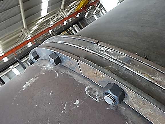
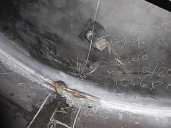
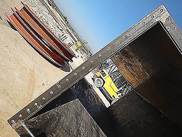
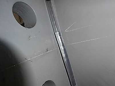
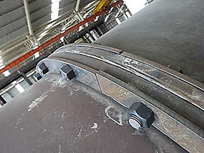
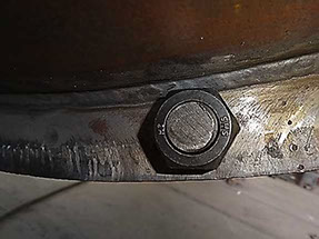
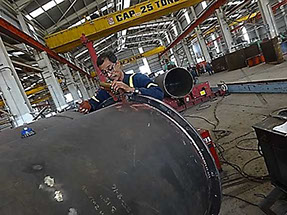
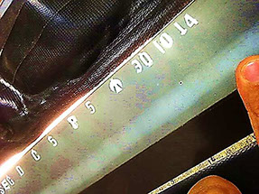
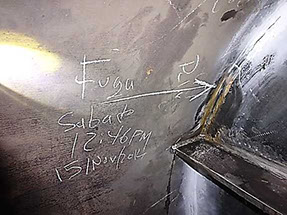
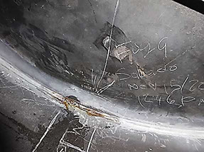
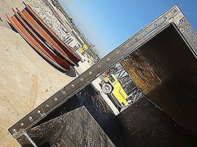
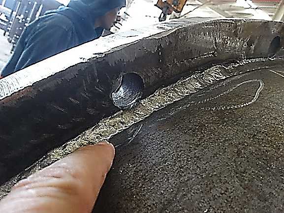
Findings: Toe of Fillet Weld of field connection Flanges(Top and Bottom) to Shell plates observed just at ends of Flange Boltholes or very close to them; This condition will produce an interference with the Bolts Head or Nuts to be installed to fasten together both Stack Sections.
Re-Inspection: After detection by Fraza Team of this Engineering Issue, per Customer Direction, in order to prevent the interference issue during the erection at jobsite,Vendor has fabricated a set of Spacer Flange Sections and assembled/bolted them together with the existing flanges on Connection Interface of Stack Section Number 1 to Section Number 2. Addressed by Vendor in accordance with Customer Direction. See Photos below as illustration.
Visual and Dimensional Inspection per ITP 841716 Rev 1 item 19 and Drawing 841716-BHL-0001 Rev 0.
Item Inspected: Stack Section Number 2.
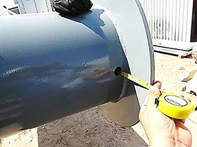
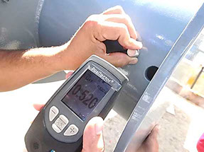
Findings: On Trunnion Item number 9 was used a Pipe 14" Sch XS(0.500") instead of Sch 80(0.75") as specified on Referenced Drawing; Fraza Team has questioned to Vendor QC Team on this Issue and as per them this Pipe Material 14" with a Wall thickness thinner than the specified one, wrongly was taken from existing stock with No Previous Inspection by Vendor QC Team before to use it.
Re-Inspection: A NCR has been open and submitted to Vendor and per Customer Disposition, the referenced Pipes 14" Sch XS (0.500") have been removed from trunnions and New Pipes 14" Sch 80(0.75") as specified have been installed and welded in accordance with referenced Drawing. See Photos as Illustration on Referenced Issue.
Dimensional Inspection per ITP 841716 Rev 1 item 013, Standard-BHL-QS-3002 and Drawing 841716-BHL-0003 Rev 1.
Item Inspected-Stack Section Number 1-Dimensions of Flange on Inlet Nozzle.
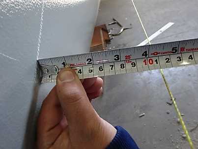
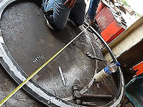
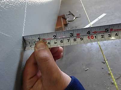
Findings: Inner Diameter, Specified Dimension, 49 1/8”, Actual as Measured, 49 11/16” (Plus 9/16”). Out of Tolerance to Project Requirements, As confirmed from Vendor QC Team, the gap of 11/32”existing between the outside surface of nozzle body item 13 and the Exceeded Inner Diameter of referenced flange, was filled by welding, which represents a major repair, Not Acceptable without a previous approval from Customer as specified on Notes Column of referenced ITP Item 13.
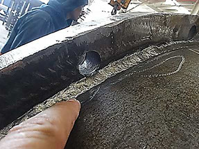
Re-Inspection: As per Customer Direction, the referenced flange was removed from Inlet Nozzle and a New Flange with right dimensions has been installed and welded in accordance with Referenced Drawing. See Photos as Illustration on Described Issue.
Benefits to Our Customer: By using Fraza Inspection Team, Customer has prevented a latent risk of accident due to faults that could be caused by using thinner tubes in the lifting trunnions; As well saved a lot of of time and money preventing excessive expenses per back charges for Re-works at field site per unacceptable issues on Welding, Dimensions, Engineering and Wrong Wall Thickness of Pipes used, If Not Corrected/Repaired in timely manner at Vendor Shop.
Project Detail
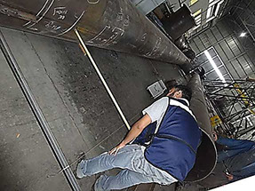
Project: Beauty High Lake Unit 03
Equipments: Back and Front End Flare Stacks, Derrick Structure and Ladder & Platforms
Date: July 2014 to January 2015
Vendor Location: Fabricator of Stacks and Structure in Nuevo Leon, Mexico.
Review on RT Examination per ITP 5394416 Rev 1, Item 11.
Item Inspected: Front End Flare Stack Assy-60” OD-Section D.
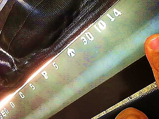
Findings: Per Review on RT Examination Reports and Films, Circumferential Seam C5, After first RT spot was rejected, Additional RT spots were RT Examined and one of them identified as C5 P5, reported originally as accepted by RT Examiner per RT report number 78043, however, during review by Fraza Team an indication ¾” length was discovered(at location 14” to 15”) on referenced RT Spot.
Re-Inspection: RT examiner was requested to re-evaluate the referenced indication and as confirmed from Him, he had accepted it by mistake during his original interpretation and it is Not Acceptable to Acceptance Criteria per ASME section VIII Div 1, UW-52, therefore that defect is to be removed and the entire length of the referenced circumferential seam is to be RT examined, As subsequently Done. Addressed by Vendor in accordance with referenced Project Requirements. See Photo on Defect Indication discovered during Fraza Team Review.
Witness on Hydrostatic Test per ITP-5394416 Rev 1, Item 15 and Customer Inspection Procedure BHL-FS-04416 Rev 0.
Item Inspected: Front End Flare Stack Assembly-60”-OD-Section A.
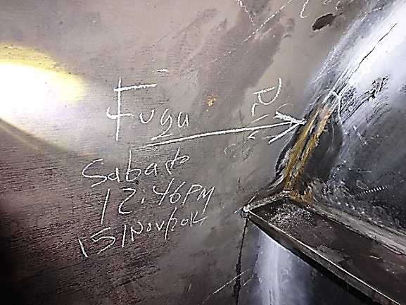
Findings: Test Results: Observed Leaks on two locations of Weld of Floor Plate to Stack Shell. Per recommendation from Fraza Team, UT Examination on referenced Weld has been conducted to confirm on Specified Full Penetration. UT Examination results reflect on lack of penetration on several spots of referenced weld included both locations observed originally with Leaks.
Re-Inspection: Vendor has done all needed Repairs, conducting a back gouging to sound metal and re-welding on all locations per Hydrotest and UT Examination findings. After Completion on Repairs, hydrostatic test has been conducted again with acceptable results. See Photos as Illustration on Areas Observed Originally with Leaks.
Witness on Straightness and Horizontal Check per ITP-5394416 Rev 1, Item 14 and Customer Inspection Procedure BHL-FS-04416 Rev 0.
Item Inspected: Front End Flare Stack Assembly-60”-OD-Section C.
Findings: Straightness Check, Maximum Allowable Lack of Straightness/Alignment-12.7 mm per Customer Inspection Procedure BHL-FS-04416 Rev 0 Note 3. Actual Straightness Deviations as Measured at Position-270 deg: 23 mm at Area of Stack Shell identified as 2/21-20/21, Out of Tolerance to referenced Customer Inspection Procedure.
Re-Inspection: Per decisión from Vendor, Defective Shell Section identified as 2/21-20/21 has been cutted off and a New Shell Section has been installed and welded to correct the referenced Straightness Deviation. After Correction, Fraza Team has Re-inspected on Straightness, and a máximum deviation of 8 mm, within tolerances per Referenced Project Requirements has been found. See Photo as Illustration on Straightness Check.
Benefits to Our Customer: By using Fraza Inspection Team, Customer saved a lot of of time and money preventing excessive expenses per back charges for Extra-RT Examination and Re-works at field site per unacceptable issues on Leaks per Hydrotest, Welding, Dimensions and Wrong Interpretation on RT Examination Results, If Not Corrected/Repaired in timely manner at Vendor Shop.
Project Detail
Project: Beauty High Lake Unit 02
Equipments: Quench Stack with Refractory, Stack 48” OD, SCR Duct and Platform & Ladders
Date: August 2016 to January 2017
Vendor Location: Fabricator of Stacks in Coahuila, Mexico.
Dimensional Inspection per ITP 232619 Rev 0 Item 014 and Drawing 232619-BH-0001 Rev 0.
Item Inspected: Square Duct-Boltholes Pattern on Field Connection Flanges.
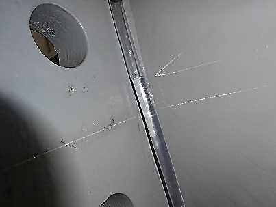
Findings: On Vertical flanges, 18 Boltholes evently spaced are specified per Referenced Drawing, however, Wrongly 19 Boltholes were done on all Four Vertical Flanges. Not Acceptable to Referenced Drawing. Vendor QC Team/Project Manager have been notified if They decide to conduct a Major Repair by Plug-Welding on existing boltholes to Correct the referenced Issue, then In accordance with ITP Requirements Item 013 Notes Column, They must submit a Request of Deviation and a Repair Procedure for Customer Approval prior to conduct any action on Repair.
Re-Inspection: Per Customer Direction, Vendor has cutted off the existing flanges and new flanges with correct bolhtoles pattern per referenced drawing have been installed and welded. See Photo on described Issue.
Benefits to Our Customer: By using Fraza Inspection Team, Customer saved a lot of of time and money preventing excessive expenses per back charges for Re-works at field site per unacceptable issues on Dimensions, If Not Corrected/Repaired in timely manner at Vendor Shop.
Project Detail
Project: Lake Charless Unit 01
Equipments: Stack/Blower Duct/Riser Piping
Date: February 2014 to May 2014
Vendor Location: Fabricator of Stack Equiments in Nuevo Leon, Mexico.
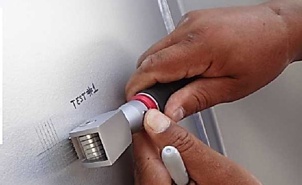
Review on Painting Records per Inspection Plan ITP-LC-8891-01 Rev 2, Item Number 16.1.
Item Inspected: Stack Section Number 2.
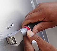
Findings: Time elapsed between Completion of Primer Coating and Starting of Intermediate Coating: Per Primer Coating Data Sheet 6.0 Hours minimum at 20 C deg is required, Actual per Painting Report-1.0 Hour at 20.0 C deg. Not Acceptable to Primer Coating Manufacturer Data Sheet. As well, Time between Completion of Intermediate Coating and Starting of Top Coating: Per Intermediate Coating Data Sheet 12.0 Hours Minimum at 20 C deg is specified, Actual per Paint Report 6.0 Hours at 20.0 C deg. Not Acceptable to Intermediate Coating Manufacturer Data Sheet.
Re-Inspection: Per Customer Direction, Vendor has conducted Two spots of adhesion test on Painted Surfaces of Stack Section Number 2, which have been witnessed by Customer Representative at Vendor Facilities and Fraza Team. Customer Representative has confirmed on Acceptance of Referenced Issue supported on acceptable results of Adhesion Test. See Photo on Adhesion Test as conducted.
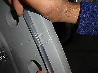
Dimensional Inspection-Flange Rotation Check per ITP-LC-8891-01 Rev 2, Item Number 13.1 and Inspection Procedure 7654-DES-QA-93 Rev 3.
Item Inspected: Stack Section Number 3.
Findings: Maximum Allowable Deviation on Flange Rotation, Smaller of 1/8”(3mm) at Bolt Circle or 1 deg per Customer Tolerances Standard RDIM-3032 Rev 2, Actual Deviations as Measured at Center Lines 0 Deg-180 Deg of Bottom and Top Flanges, 20.5mm-Out of Tolerance to Project Specifications Referenced above.
Re-Inspection: Corrections completed by Vendor in accordance with Project Requirements. See Photo on Referenced Issue.
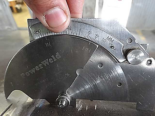
Visual and Dimensional Inspection on Weld Preparation and Fit-up per Inspection Plan ITP-LC-8891-01 Rev 2, Item Number 5.1 and Drawing 8890-02-TU-01 Rev 2.
Item Inspected: 84” OD Stack Section Number 3.
Findings: Third Circumferential Joint observed with mismatches between both parts being fitted-up, greater than 1/4T. Not Acceptable to Alignment Tolerances per ASME Section VIII Div 1- Paragraph UW-33.
Re-Inspection: Corrections conducted by Vendor to bring the referenced weld preparations to within alignment tolerances per Project Requirements. See Photo showing on Referenced Issue.
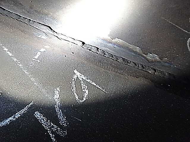
Visual Inspection on Welds per Inspection Plan ITP-LC-8891-01 Rev 2, Item Number 13.1 and Drawing 8890-02-TU-01 Rev 2.
Item Inspected: 84” OD Stack Sections Number 2 and 3.
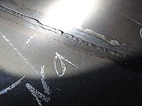
Findings: Circumferential Seams observed with Not Acceptable Undercuts, Underfill and Arc Strikes.
Re-Inspection: Repairs completed by Vendor in accordance with Project Requirements. See Photo as illustration on Referenced typical Issues
Visual and Dimensional Inspection on Welds per ITP-LC-8891-01 Rev 2, Item Number 13.1 and Drawing 8892-02-TU-02 Rev 3.
Item Inspected: Stack Section Number 4.
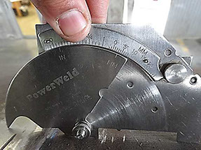
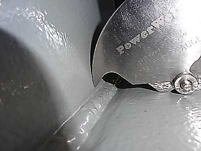
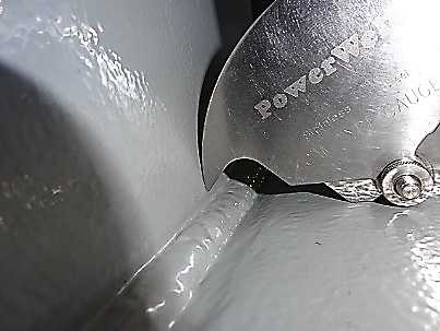
Findings: Specified Fillet Weld Size on Joints of Lower Flange and Supports to Stack Shell: 1/4”, Actual as Measured- Undersized Fillet Weld Size Less than 3/16”.
Re-Inspection: Repairs completed by Vendor in accordance with Referenced Drawing Requirements. See Photo on Described Issue.
Straightness and Horizontal Check per ITP-LC-8891-01 Rev 2 Item Number 12.1, Inspection Procedure 7654-DES-QA-93 Rev 3 and Drawing 8892-02-TU-02 Rev 3.
Item Inspected: Stack Section Number 3.
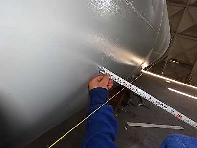
Findings: Maximum Allowable Deviation on Lack of Straightness-16mm per Customer Tolerances Standard RDIM-3032 Rev 2, Actual Straightness Deviation as Measured at Position-0 deg: 32mm-Out of Tolerance per Project Specifications.
Re-Inspection: Corrections completed by Vendor to bring Straightness Deviation to within referenced tolerances. See Photo as illustration on Straightness Check.
Review on Engineering Requirements per Inspection Plan ITP-LC-8891-01 Rev 2, Item Number 1.1.
Items Inspected: Engineering Drawings.
Findings: Several Discrepancies in Orientation have been detected between General Assembly Drawing and Individual Stack Drawings as follows: Gas Riser Pipe Supports oriented at 180 deg on Individual Drawings 8892-02-TU-02/03/04 Rev 3 of Stack Sections Number 1, 2, 3 and 4, however Oriented at 0 deg on GA Drawing 9002-01 Rev 1.Trunnions oriented at 0 and 180 deg on Individual Drawing of Stack Sections Number 3, however Oriented at 90 and 270 deg on GA Drawing.
Re-Inspection: Taking into account the Observation above from Fraza Team, Customer has addressed on this Engineering Issue and has issued updated revisions of Individual and GA Drawings confirming on Right Orientation of all referenced attachments.This Observation from Fraza Team has prevented on confusions and mistakes during the Fabrication Process.
Review on Project Requirements per Inspection Plan ITP-LC-8891-01 Rev 2, Item Number 1.1 and Drawing 8891-01-LC1-01 Rev 0 Air Gas Riser.
Item Inspected: Gas Riser Equipments-Purchasing Documents.
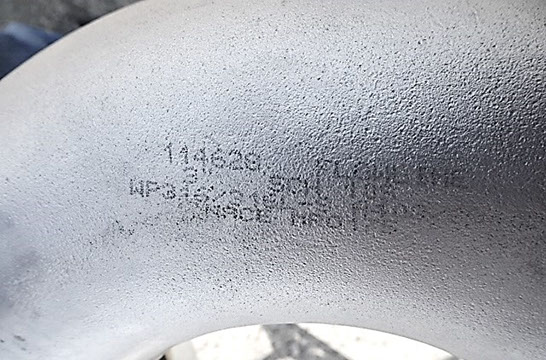
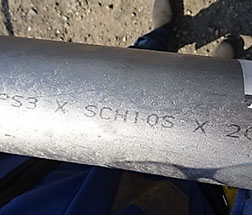
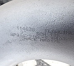
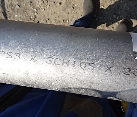
Findings: Per Drawing 8891-LC1-01 Rev 0, all Pipe/Fitting Items for Gas Riser are specified to be in Schedule 40 wall thickness, however per an incorrect interpretation of Project Requirements, Vendor had been purchasing all pipe/fitting ítems in schedule 10. Per Observation from Fraza Team, Vendor has corrected the Purchase Documents to reflect on Right Schedule for all Pipe Items in accordance with Project Documents. See Photos on Some Pipe/Fitting Items as Received at Vendor Facilities.
Project Detail
Project: Hidden River
Equipments: F Stack
Date: December 2012 to September 2013
Vendor Location: Fabricator of Stacks and Pressure Vessels in Nuevo Leon, Mexico.
Dimensional Inspection per Inspection Plan DUT-KG-H7664-ITP Rev 3 Item Number 6.1.7 and Drawing 6GT-AK5678-01 Rev 6.
Item Inspected: Fabricated Stack, Conical Section.
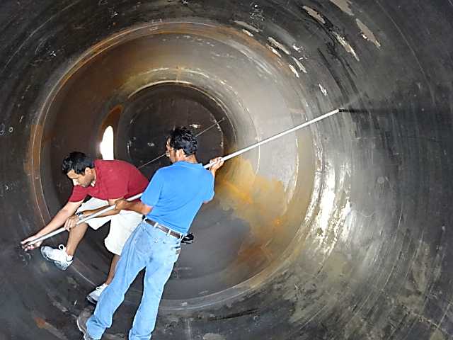
Findings: A condition Out-of-Roundness of 1.78% found at a cross-section beside the conical section (change of diameter), exceeding the maximum allowable deviation of 1% per Customer Specification MJM-RT-2204 Note 20 and ASME Code Section VIII Div 1-UG-80. Specified Inner Diameter, 2743mm, Actual Deviations as measured at 30 deg-210 deg position 2767 mm (Plus 24 mm) as well at 120 deg-300 deg position 2718 mm (Minus 25 mm).
Re-Inspection: Corrected by Vendor to bring Out-of-Roundness deviation within referenced Project Tolerances. See Photo as illustration on dimensional inspection as conducted.
Witness on Measuring of Dry Film Thickness per Inspection Plan DUT-KG-H7664-ITP Rev 3, Item Numbers 9.1.7 and Customer Specification MJM-RT-2204 Rev 4.
Item Inspected: Painted Bottom Stack Section.
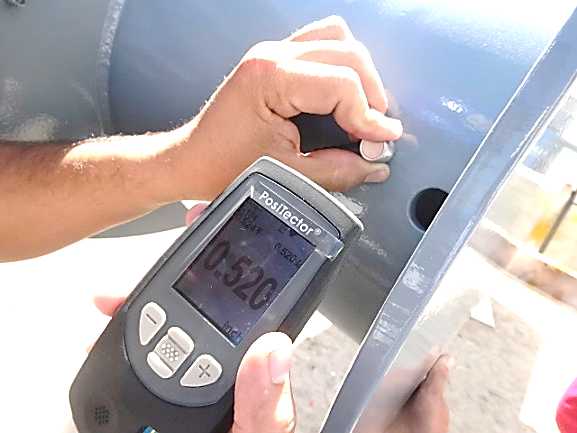
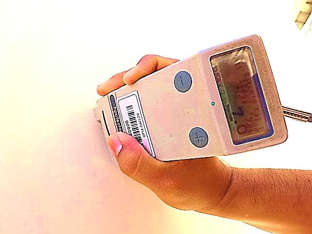
Findings: Specified Total DFT-12 to14 Mils per Customer Specification MJM-RT-2204 Section 8.0, Actual DFT Measurements: Several áreas with Low DFT, 7.0 to 8.0 Mils, out of specification.
Re-Inspection: Corrections by re-painting to bring DFT within specified Range per referenced Specification and Standard SSPC-PA2 completed by Vendor. See Photo showing on Referenced Issue.
Visual Inspection on Painting per Inspection Plan DUT-KG-H7664-ITP Rev 3, Item Numbers 9.1.8 and Customer Specification MJM-RT-2204 Rev 4.
Item Inspected: Painted Stack Base Section.
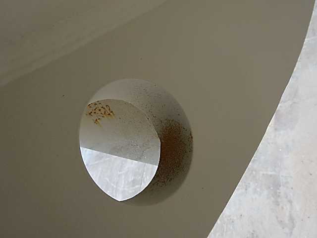
Findings: Areas such as Internal surface of Anchor Boltholes of Base Section, internal edges of helical strakes and Lifting Lugs observed with rusting per no full painting coverage.
Re-Inspection: Repairs completed by Vendor by sanding and re-painting in accordance with Paint Manufacturer Data Sheet and Project Documents above. See Photo on described Issue.
Visual Inspection on Painting per Inspection Plan DUT-KG-H7664-ITP Rev 3, Item Numbers 9.1.8 and Customer Specification MJM-RT-2204 Rev 4.
Item Inspected: Painted Stack Top Section.
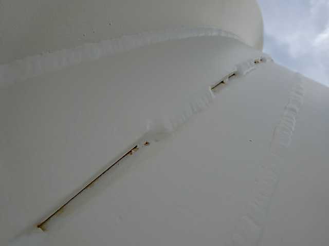
Findings: Rusting bleeding out from stitch welds of external Reinforcing Rings of Stack Top Section.
Re-Inspection: Per Customer Direction, Vendor has completed on seal weld on both sides of joints of referenced External Reinforcing Rings, as well the re-welded areas have been surface prepared by Re-blasting before painting application per specified Paint System. See Photo as Illustration on Described Issue as originally found.
Benefits to Our Customer: By using Fraza Inspection Team, Customer saved a lot of of time and money preventing excessive expenses per back charges for Reworks at field site per unacceptable issues on dimensions and painting If Not Repaired in timely manner at Vendor Shop.
© 2019 Fraza Inspection Company - All Rights Reserved
Project #1
Project Detail
Project: Beauty High Lake Unit 01
Equipments: Sub Stack and 16” Gas Riser Assembly
Date: August 2016 to October 2016
Vendor Location: Fabricator of Stacks and Piping Items in Coahuila, Mexico.
Item #1
Visual Inspection per ITP 841716 Rev 1 Item 012 and Drawing 841716-BHL-1-716-0001 Rev 0.
Item Inspected-Stack Section Number 2.
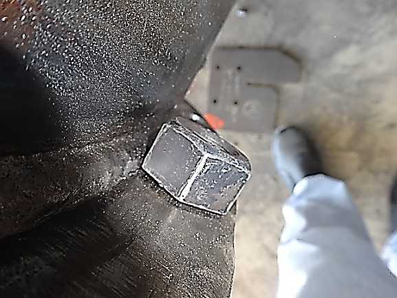
Findings: Toe of Fillet Weld of field connection Flanges(Top and Bottom) to Shell plates observed just at ends of Flange Boltholes or very close to them; This condition will produce an interference with the Bolts Head or Nuts to be installed to fasten together both Stack Sections.
Re-Inspection: After detection by Fraza Team of this Engineering Issue, per Customer Direction, in order to prevent the interference issue during the erection at jobsite,Vendor has fabricated a set of Spacer Flange Sections and assembled/bolted them together with the existing flanges on Connection Interface of Stack Section Number 1 to Section Number 2. Addressed by Vendor in accordance with Customer Direction. See Photos below as illustration.
Item #2
Visual and Dimensional Inspection per ITP 841716 Rev 1 item 19 and Drawing 841716-BHL-0001 Rev 0.
Item Inspected: Stack Section Number 2.
Findings: On Trunnion Item number 9 was used a Pipe 14" Sch XS(0.500") instead of Sch 80(0.75") as specified on Referenced Drawing; Fraza Team has questioned to Vendor QC Team on this Issue and as per them this Pipe Material 14" with a Wall thickness thinner than the specified one, wrongly was taken from existing stock with No Previous Inspection by Vendor QC Team before to use it.
Re-Inspection: A NCR has been open and submitted to Vendor and per Customer Disposition, the referenced Pipes 14" Sch XS (0.500") have been removed from trunnions and New Pipes 14" Sch 80(0.75") as specified have been installed and welded in accordance with referenced Drawing. See Photos as Illustration on Referenced Issue.
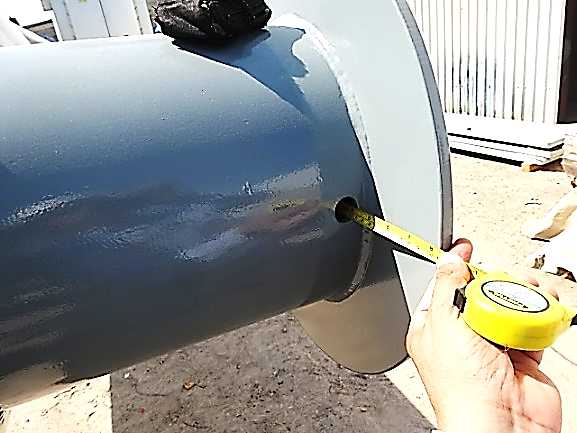
Item #3
Dimensional Inspection per ITP 841716 Rev 1 item 013, Standard-BHL-QS-3002 and Drawing 841716-BHL-0003 Rev 1.
Item Inspected-Stack Section Number 1-Dimensions of Flange on Inlet Nozzle.
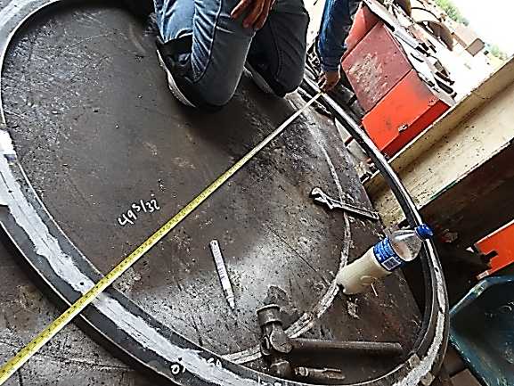
Findings: Inner Diameter, Specified Dimension, 49 1/8”, Actual as Measured, 49 11/16” (Plus 9/16”). Out of Tolerance to Project Requirements, As confirmed from Vendor QC Team, the gap of 11/32”existing between the outside surface of nozzle body item 13 and the Exceeded Inner Diameter of referenced flange, was filled by welding, which represents a major repair, Not Acceptable without a previous approval from Customer as specified on Notes Column of referenced ITP Item 13.
Re-Inspection: As per Customer Direction, the referenced flange was removed from Inlet Nozzle and a New Flange with right dimensions has been installed and welded in accordance with Referenced Drawing. See Photos as Illustration on Described Issue.
Benefits to Our Customer: By using Fraza Inspection Team, Customer has prevented a latent risk of accident due to faults that could be caused by using thinner tubes in the lifting trunnions; As well saved a lot of of time and money preventing excessive expenses per back charges for Re-works at field site per unacceptable issues on Welding, Dimensions, Engineering and Wrong Wall Thickness of Pipes used, If Not Corrected/Repaired in timely manner at Vendor Shop.
Project #2
Project Detail
Project: Beauty High Lake Unit 03
Equipments: Back and Front End Flare Stacks, Derrick Structure and Ladder & Platforms
Date: July 2014 to January 2015
Vendor Location: Fabricator of Stacks and Structure in Nuevo Leon, Mexico.
Item #1
Review on RT Examination per ITP 5394416 Rev 1, Item 11.
Item Inspected: Front End Flare Stack Assy-60” OD-Section D.
Findings: Per Review on RT Examination Reports and Films, Circumferential Seam C5, After first RT spot was rejected, Additional RT spots were RT Examined and one of them identified as C5 P5, reported originally as accepted by RT Examiner per RT report number 78043, however, during review by Fraza Team an indication ¾” length was discovered(at location 14” to 15”) on referenced RT Spot.
Re-Inspection: RT examiner was requested to re-evaluate the referenced indication and as confirmed from Him, he had accepted it by mistake during his original interpretation and it is Not Acceptable to Acceptance Criteria per ASME section VIII Div 1, UW-52, therefore that defect is to be removed and the entire length of the referenced circumferential seam is to be RT examined, As subsequently Done. Addressed by Vendor in accordance with referenced Project Requirements. See Photo on Defect Indication discovered during Fraza Team Review.
Item #2
Witness on Hydrostatic Test per ITP-5394416 Rev 1, Item 15 and Customer Inspection Procedure BHL-FS-04416 Rev 0.
Item Inspected: Front End Flare Stack Assembly-60”-OD-Section A.
Findings: Test Results: Observed Leaks on two locations of Weld of Floor Plate to Stack Shell. Per recommendation from Fraza Team, UT Examination on referenced Weld has been conducted to confirm on Specified Full Penetration. UT Examination results reflect on lack of penetration on several spots of referenced weld included both locations observed originally with Leaks.
Re-Inspection: Vendor has done all needed Repairs, conducting a back gouging to sound metal and re-welding on all locations per Hydrotest and UT Examination findings. After Completion on Repairs, hydrostatic test has been conducted again with acceptable results. See Photos as Illustration on Areas Observed Originally with Leaks.
Item #3
Witness on Straightness and Horizontal Check per ITP-5394416 Rev 1, Item 14 and Customer Inspection Procedure BHL-FS-04416 Rev 0.
Item Inspected: Front End Flare Stack Assembly-60”-OD-Section C.
Findings: Straightness Check, Maximum Allowable Lack of Straightness/Alignment-12.7 mm per Customer Inspection Procedure BHL-FS-04416 Rev 0 Note 3. Actual Straightness Deviations as Measured at Position-270 deg: 23 mm at Area of Stack Shell identified as 2/21-20/21, Out of Tolerance to referenced Customer Inspection Procedure.
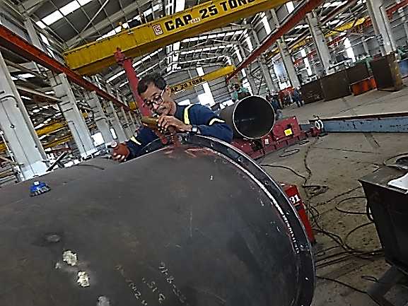
Re-Inspection: Per decisión from Vendor, Defective Shell Section identified as 2/21-20/21 has been cutted off and a New Shell Section has been installed and welded to correct the referenced Straightness Deviation. After Correction, Fraza Team has Re-inspected on Straightness, and a máximum deviation of 8 mm, within tolerances per Referenced Project Requirements has been found. See Photo as Illustration on Straightness Check.
Benefits to Our Customer: By using Fraza Inspection Team, Customer saved a lot of of time and money preventing excessive expenses per back charges for Extra-RT Examination and Re-works at field site per unacceptable issues on Leaks per Hydrotest, Welding, Dimensions and Wrong Interpretation on RT Examination Results, If Not Corrected/Repaired in timely manner at Vendor Shop.
Project #3
Project Detail
Project: Beauty High Lake Unit 02
Equipments: Quench Stack with Refractory, Stack 48” OD, SCR Duct and Platform & Ladders
Date: August 2016 to January 2017
Vendor Location: Fabricator of Stacks in Coahuila, Mexico.
Item #1
Dimensional Inspection per ITP 232619 Rev 0 Item 014 and Drawing 232619-BH-0001 Rev 0.
Item Inspected: Square Duct-Boltholes Pattern on Field Connection Flanges.
Findings: On Vertical flanges, 18 Boltholes evently spaced are specified per Referenced Drawing, however, Wrongly 19 Boltholes were done on all Four Vertical Flanges. Not Acceptable to Referenced Drawing. Vendor QC Team/Project Manager have been notified if They decide to conduct a Major Repair by Plug-Welding on existing boltholes to Correct the referenced Issue, then In accordance with ITP Requirements Item 013 Notes Column, They must submit a Request of Deviation and a Repair Procedure for Customer Approval prior to conduct any action on Repair.
Re-Inspection: Per Customer Direction, Vendor has cutted off the existing flanges and new flanges with correct bolhtoles pattern per referenced drawing have been installed and welded. See Photo on described Issue.
Benefits to Our Customer: By using Fraza Inspection Team, Customer saved a lot of of time and money preventing excessive expenses per back charges for Re-works at field site per unacceptable issues on Dimensions, If Not Corrected/Repaired in timely manner at Vendor Shop.
Project #4
Project Detail
Project: Lake Charless Unit 01
Equipments: Stack/Blower Duct/Riser Piping
Date: February 2014 to May 2014
Vendor Location: Fabricator of Stack Equiments in Nuevo Leon, Mexico.
Item #1
Review on Painting Records per Inspection Plan ITP-LC-8891-01 Rev 2, Item Number 16.1.
Item Inspected: Stack Section Number 2.
Findings: Time elapsed between Completion of Primer Coating and Starting of Intermediate Coating: Per Primer Coating Data Sheet 6.0 Hours minimum at 20 C deg is required, Actual per Painting Report-1.0 Hour at 20.0 C deg. Not Acceptable to Primer Coating Manufacturer Data Sheet. As well, Time between Completion of Intermediate Coating and Starting of Top Coating: Per Intermediate Coating Data Sheet 12.0 Hours Minimum at 20 C deg is specified, Actual per Paint Report 6.0 Hours at 20.0 C deg. Not Acceptable to Intermediate Coating Manufacturer Data Sheet.
Re-Inspection: Per Customer Direction, Vendor has conducted Two spots of adhesion test on Painted Surfaces of Stack Section Number 2, which have been witnessed by Customer Representative at Vendor Facilities and Fraza Team. Customer Representative has confirmed on Acceptance of Referenced Issue supported on acceptable results of Adhesion Test. See Photo on Adhesion Test as conducted.
Item #2
Dimensional Inspection-Flange Rotation Check per ITP-LC-8891-01 Rev 2, Item Number 13.1 and Inspection Procedure 7654-DES-QA-93 Rev 3.
Item Inspected: Stack Section Number 3.
Findings: Maximum Allowable Deviation on Flange Rotation, Smaller of 1/8”(3mm) at Bolt Circle or 1 deg per Customer Tolerances Standard RDIM-3032 Rev 2, Actual Deviations as Measured at Center Lines 0 Deg-180 Deg of Bottom and Top Flanges, 20.5mm-Out of Tolerance to Project Specifications Referenced above.
Re-Inspection: Corrections completed by Vendor in accordance with Project Requirements. See Photo on Referenced Issue.
Item #3
Visual and Dimensional Inspection on Weld Preparation and Fit-up per Inspection Plan ITP-LC-8891-01 Rev 2, Item Number 5.1 and Drawing 8890-02-TU-01 Rev 2.
Item Inspected: 84” OD Stack Section Number 3.
Findings: Third Circumferential Joint observed with mismatches between both parts being fitted-up, greater than 1/4T. Not Acceptable to Alignment Tolerances per ASME Section VIII Div 1- Paragraph UW-33.
Re-Inspection: Corrections conducted by Vendor to bring the referenced weld preparations to within alignment tolerances per Project Requirements. See Photo showing on Referenced Issue.
Item #4
Visual Inspection on Welds per Inspection Plan ITP-LC-8891-01 Rev 2, Item Number 13.1 and Drawing 8890-02-TU-01 Rev 2.
Item Inspected: 84” OD Stack Sections Number 2 and 3.
Findings: Circumferential Seams observed with Not Acceptable Undercuts, Underfill and Arc Strikes.
Re-Inspection: Repairs completed by Vendor in accordance with Project Requirements. See Photo as illustration on Referenced typical Issues
Item #5
Visual and Dimensional Inspection on Welds per ITP-LC-8891-01 Rev 2, Item Number 13.1 and Drawing 8892-02-TU-02 Rev 3.
Item Inspected: Stack Section Number 4.
Findings: Specified Fillet Weld Size on Joints of Lower Flange and Supports to Stack Shell: 1/4”, Actual as Measured- Undersized Fillet Weld Size Less than 3/16”.
Re-Inspection: Repairs completed by Vendor in accordance with Referenced Drawing Requirements. See Photo on Described Issue.
Item #6
Straightness and Horizontal Check per ITP-LC-8891-01 Rev 2 Item Number 12.1, Inspection Procedure 7654-DES-QA-93 Rev 3 and Drawing 8892-02-TU-02 Rev 3.
Item Inspected: Stack Section Number 3.
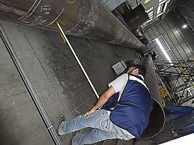
Findings: Maximum Allowable Deviation on Lack of Straightness-16mm per Customer Tolerances Standard RDIM-3032 Rev 2, Actual Straightness Deviation as Measured at Position-0 deg: 32mm-Out of Tolerance per Project Specifications.
Re-Inspection: Corrections completed by Vendor to bring Straightness Deviation to within referenced tolerances. See Photo as illustration on Straightness Check.
Item #7
Review on Engineering Requirements per Inspection Plan ITP-LC-8891-01 Rev 2, Item Number 1.1.
Items Inspected: Engineering Drawings.
Findings: Several Discrepancies in Orientation have been detected between General Assembly Drawing and Individual Stack Drawings as follows: Gas Riser Pipe Supports oriented at 180 deg on Individual Drawings 8892-02-TU-02/03/04 Rev 3 of Stack Sections Number 1, 2, 3 and 4, however Oriented at 0 deg on GA Drawing 9002-01 Rev 1.Trunnions oriented at 0 and 180 deg on Individual Drawing of Stack Sections Number 3, however Oriented at 90 and 270 deg on GA Drawing.
Re-Inspection: Taking into account the Observation above from Fraza Team, Customer has addressed on this Engineering Issue and has issued updated revisions of Individual and GA Drawings confirming on Right Orientation of all referenced attachments.This Observation from Fraza Team has prevented on confusions and mistakes during the Fabrication Process.

Item #8
Review on Project Requirements per Inspection Plan ITP-LC-8891-01 Rev 2, Item Number 1.1 and Drawing 8891-01-LC1-01 Rev 0 Air Gas Riser.
Item Inspected: Gas Riser Equipments-Purchasing Documents.
Findings: Per Drawing 8891-LC1-01 Rev 0, all Pipe/Fitting Items for Gas Riser are specified to be in Schedule 40 wall thickness, however per an incorrect interpretation of Project Requirements, Vendor had been purchasing all pipe/fitting ítems in schedule 10. Per Observation from Fraza Team, Vendor has corrected the Purchase Documents to reflect on Right Schedule for all Pipe Items in accordance with Project Documents. See Photos on Some Pipe/Fitting Items as Received at Vendor Facilities.
Project #5
Project Detail
Project: Hidden River
Equipments: F Stack
Date: December 2012 to September 2013
Vendor Location: Fabricator of Stacks and Pressure Vessels in Nuevo Leon, Mexico.
Item #1
Dimensional Inspection per Inspection Plan DUT-KG-H7664-ITP Rev 3 Item Number 6.1.7 and Drawing 6GT-AK5678-01 Rev 6.
Item Inspected: Fabricated Stack, Conical Section.
Findings: A condition Out-of-Roundness of 1.78% found at a cross-section beside the conical section (change of diameter), exceeding the maximum allowable deviation of 1% per Customer Specification MJM-RT-2204 Note 20 and ASME Code Section VIII Div 1-UG-80. Specified Inner Diameter, 2743mm, Actual Deviations as measured at 30 deg-210 deg position 2767 mm (Plus 24 mm) as well at 120 deg-300 deg position 2718 mm (Minus 25 mm).
Re-Inspection: Corrected by Vendor to bring Out-of-Roundness deviation within referenced Project Tolerances. See Photo as illustration on dimensional inspection as conducted.
Item #2
Witness on Measuring of Dry Film Thickness per Inspection Plan DUT-KG-H7664-ITP Rev 3, Item Numbers 9.1.7 and Customer Specification MJM-RT-2204 Rev 4.
Item Inspected: Painted Bottom Stack Section.
Findings: Specified Total DFT-12 to14 Mils per Customer Specification MJM-RT-2204 Section 8.0, Actual DFT Measurements: Several áreas with Low DFT, 7.0 to 8.0 Mils, out of specification.
Re-Inspection: Corrections by re-painting to bring DFT within specified Range per referenced Specification and Standard SSPC-PA2 completed by Vendor. See Photo showing on Referenced Issue.
Item #3
Visual Inspection on Painting per Inspection Plan DUT-KG-H7664-ITP Rev 3, Item Numbers 9.1.8 and Customer Specification MJM-RT-2204 Rev 4.
Item Inspected: Painted Stack Base Section.
Findings: Areas such as Internal surface of Anchor Boltholes of Base Section, internal edges of helical strakes and Lifting Lugs observed with rusting per no full painting coverage.
Re-Inspection: Repairs completed by Vendor by sanding and re-painting in accordance with Paint Manufacturer Data Sheet and Project Documents above. See Photo on described Issue.
Item #4
Visual Inspection on Painting per Inspection Plan DUT-KG-H7664-ITP Rev 3, Item Numbers 9.1.8 and Customer Specification MJM-RT-2204 Rev 4.
Item Inspected: Painted Stack Top Section.
Findings: Rusting bleeding out from stitch welds of external Reinforcing Rings of Stack Top Section.
Re-Inspection: Per Customer Direction, Vendor has completed on seal weld on both sides of joints of referenced External Reinforcing Rings, as well the re-welded areas have been surface prepared by Re-blasting before painting application per specified Paint System. See Photo as Illustration on Described Issue as originally found.
Benefits to Our Customer: By using Fraza Inspection Team, Customer saved a lot of of time and money preventing excessive expenses per back charges for Reworks at field site per unacceptable issues on dimensions and painting If Not Repaired in timely manner at Vendor Shop.